Gutting the inside of a Krop helmet

Tips, tricks, inside secrets, help, sources, items used on making the Cylon Centurion suit to wear. Tell us your story, how you came about collecting your parts to a Centurion, or if you own a complete Centurion costume.
User avatar
MackUK
Phalanx Member
Posts: 86
Joined: Tue Nov 21, 2017 12:43 pm
Location: London, UK

Gutting the inside of a Krop helmet

Post by MackUK » Fri Aug 17, 2018 4:30 am

So I've decided that it's time to start gutting the inside of a standard Krop helmet and make it more comfortable, not only to wear but include the following...


Controls for the RedEye, Fans, Padding, Microphone for VT-3 Vocoder, Earphones in stereo, Mics for earphones (will be difficult to hear with all the padding), power packs (Or seperate power from a 12v Li-ion power pack in either the front chest plate, or rear back pack).

The standard helmet looks like this.. and is pretty basic, it wobbles when wearing and for me at least is noisy when breathing, and heats up fast.
Image

I'll keep you posted on my progress as the parts arrive.


User avatar
Cylon-Knight
Site Administrator
Posts: 6419
Joined: Wed Jul 23, 2008 9:32 pm
Location: Kansas City
Contact:

Re: Gutting the inside of a Krop helmet

Post by Cylon-Knight » Fri Aug 17, 2018 6:52 pm

Oh my - the inside of that is pretty sweet now... It'll be interesting to see how you take it to the next level, yes indeed.

:CK: ;)
"All Baseships are now in range to attack the Colonies."
Image

User avatar
MackUK
Phalanx Member
Posts: 86
Joined: Tue Nov 21, 2017 12:43 pm
Location: London, UK

Re: Gutting the inside of a Krop helmet

Post by MackUK » Sun Aug 19, 2018 3:10 pm

So the Planned basic wiring diagram looks like this for the sound system to "listen". I'm still waiting for a couple of parts to come in (I'll post the list of parts I used and the source I got them from) as soon as I have the full kit and am ready to go ahead and do this.

Overall, all of the components will be inside the helmet (there's a ton of space in there to put them) but for the R & L Mics, there will be a couple of holes to drill either side @ 1mm so they don't look obvious and will likely put them on the corner of the side grey panels where they meet the chrome.

Image

User avatar
MackUK
Phalanx Member
Posts: 86
Joined: Tue Nov 21, 2017 12:43 pm
Location: London, UK

Re: Gutting the inside of a Krop helmet

Post by MackUK » Sun Aug 19, 2018 3:32 pm

As for the fans, the Planned wiring is simple. Power comes up from the RHS arm Armour switch and feeds two 9-12V squirrel fans which will push the cool air over the forehead. This will not interfere with the mic for the VT-3 Vocoder.


Image

User avatar
Soda Can
Phalanx Leader
Posts: 120
Joined: Wed Jun 10, 2015 2:56 am
Location: Otaki, New Zealand
Contact:

Re: Gutting the inside of a Krop helmet

Post by Soda Can » Mon Aug 20, 2018 3:15 am

:loveit: that is going to look great, nice diagram so far and quite a good plan for the fan.
Be great to see it.
Lots of photos, I like pictures, keeps the attention span going, comic book mentality.
If anybody can, Soda Can Cylon can. :cylon:

User avatar
MackUK
Phalanx Member
Posts: 86
Joined: Tue Nov 21, 2017 12:43 pm
Location: London, UK

Re: Gutting the inside of a Krop helmet

Post by MackUK » Sat Aug 25, 2018 5:21 am

A quick update...

I've got most of the parts now.. I'm just waiting for the Amps for the speakers to arrive (they're somewhere in the Pacific right now, so I know they're on their way!

Can't wait to show the end result … Looking forward to this little (yet pain)Project!

So before I began, I rounded up some of the tools and equipment that I'll need and they are....

Image

1 Cable connectors ranging 2-6 pin
2 Positive (Red) wire
3 Negative (Black) wire
4 Squirrel Fans
5 Drill with 1mm SDS drill bit
6 Wire cutters
7 Glue / Hot Glue
8 Microphones (yes they're that small) - ARRIVED
9 Pre Speaker Amp boards (yes they are that small) - ARRIVED
10 Speakers
11 Wireless Motorcycle helmet microphone
12 Illuminated rocker switches
13 Heat shrink for soldered wires
14 Battery packs x 2 -3
15 Velcro
16 5-6.5 mm Flexi wire conduit
17 Heatgun


What I didn't get in the picture was...

Cosplay foam 2x 1 m
Soldering iron


So...
Last edited by MackUK on Tue Sep 04, 2018 12:03 pm, edited 2 times in total.

User avatar
Cylon-Knight
Site Administrator
Posts: 6419
Joined: Wed Jul 23, 2008 9:32 pm
Location: Kansas City
Contact:

Re: Gutting the inside of a Krop helmet

Post by Cylon-Knight » Sat Aug 25, 2018 3:57 pm

Oh my goodness - WOW. I can't wait to see if all that fits...
I guess I just have a big head. :oops: I can't imagine all that in my helmet. :huh:
"All Baseships are now in range to attack the Colonies."
Image

User avatar
MackUK
Phalanx Member
Posts: 86
Joined: Tue Nov 21, 2017 12:43 pm
Location: London, UK

Re: Gutting the inside of a Krop helmet

Post by MackUK » Mon Aug 27, 2018 11:24 am

OK, so after working out the wiring and how to minimise space in both the RH Gauntlet and helmet.. this is what I've come up with.

Illuminated switches (4 in total) will be on the Right Hand Gauntlet (its bigger than the LH one, so seems an ideal place for 2-3 PP3 batteries wired in "PARALLEL" and not in a "SERIES".. we want to increase mA/h not voltage!

One thing I forgot to add to the key was the big black dots which are soldered wires as opposed to connectors. This will obviously save a ton of space.

For the mics, earphones, amps and volume control, I'll add the wiring as soon as I've got all the parts!


Image

Arm wiring loom (in 5mm conduit) will be velcro'ed to the inside of the under suit on the right arm so it's removable for washing etc and a simple 6-9 pin connector just pops into place on the gauntlet, and the bottom of the helmet. I'll show in pictures as soon as all the bits arrive, but most of these are easily achieved with auto 12v wires and calculating the correct lengths given to personal preferences.

Switches are illuminated, so show at a glance what unit is on / off.

Anyway, more on this soon!

User avatar
MackUK
Phalanx Member
Posts: 86
Joined: Tue Nov 21, 2017 12:43 pm
Location: London, UK

Re: Gutting the inside of a Krop helmet

Post by MackUK » Tue Aug 28, 2018 3:43 pm

So here's the wiring diagram for the earphones and speakers I'll use to hear the outside world. I was surprised just how small the amp boards were when they arrived from ebay today (thumb nail size) and each comes with it's own volume control too, so they'll have to be fitted with the volume controller accessible (not a problem given where I am going to fit them).

So I'm nearly ready to start the soldering and wiring.

I'll keep you posted ! :salute:

Image

User avatar
Soda Can
Phalanx Leader
Posts: 120
Joined: Wed Jun 10, 2015 2:56 am
Location: Otaki, New Zealand
Contact:

Re: Gutting the inside of a Krop helmet

Post by Soda Can » Wed Aug 29, 2018 3:58 am

That is going to be quite the technically advanced cylon there, nice plan so far, just don't mix up your gauntlets.
If anybody can, Soda Can Cylon can. :cylon:

User avatar
MackUK
Phalanx Member
Posts: 86
Joined: Tue Nov 21, 2017 12:43 pm
Location: London, UK

Re: Gutting the inside of a Krop helmet

Post by MackUK » Fri Aug 31, 2018 2:11 pm

:evillaugh: Gauntlets are well and truly placed on the correct hands (checked and double checked)

So... to the build...

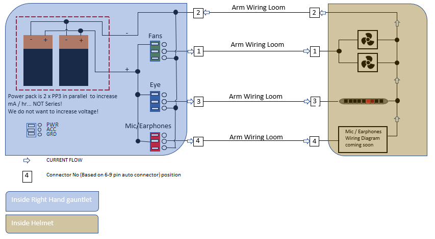
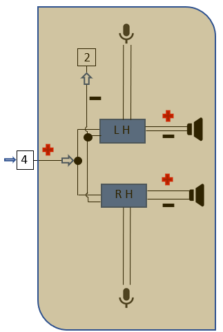
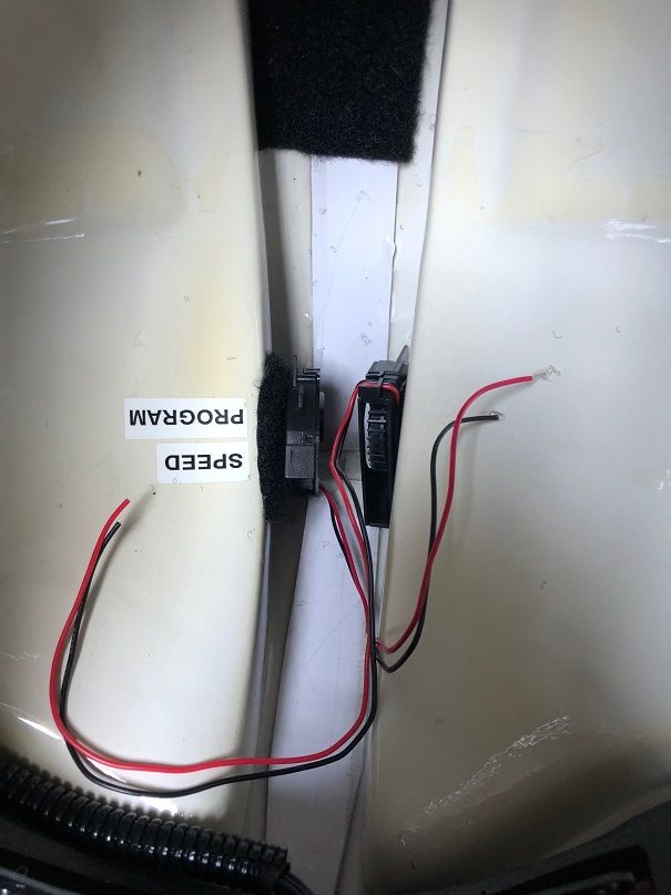
Firstly as I stated already, I want to be able to control all electronic functions easily. To do this, I'll used the right gauntlet to add a few switches in which, I am able to switch on/off the fans, same with the eye scanner and the same with the headphones and mic. I'll also have one redundant switch should I wish to use it for something else, but it's mostly aesthetics at the moment.


I'm also using a small cut out to control the MP3 which makes the cylon scanning sound. but more on this later.


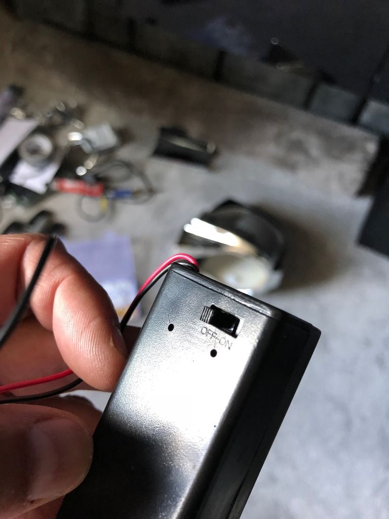
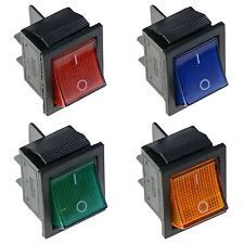
Using ebay I sourced some illuminated rocker switches (£3 for four)

Image

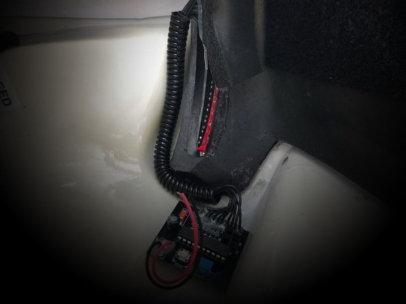
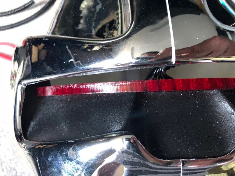
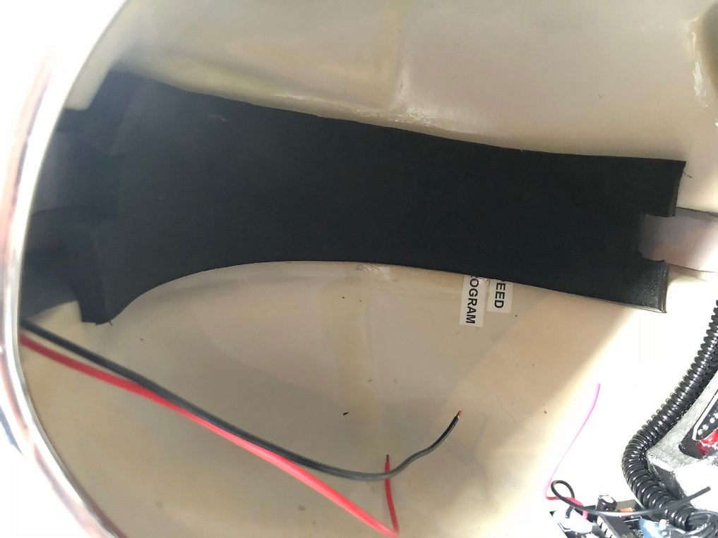
Once they arrived, the first thing I needed to do was decide where to place them. I've put two on the top of the Gauntlet...

Image

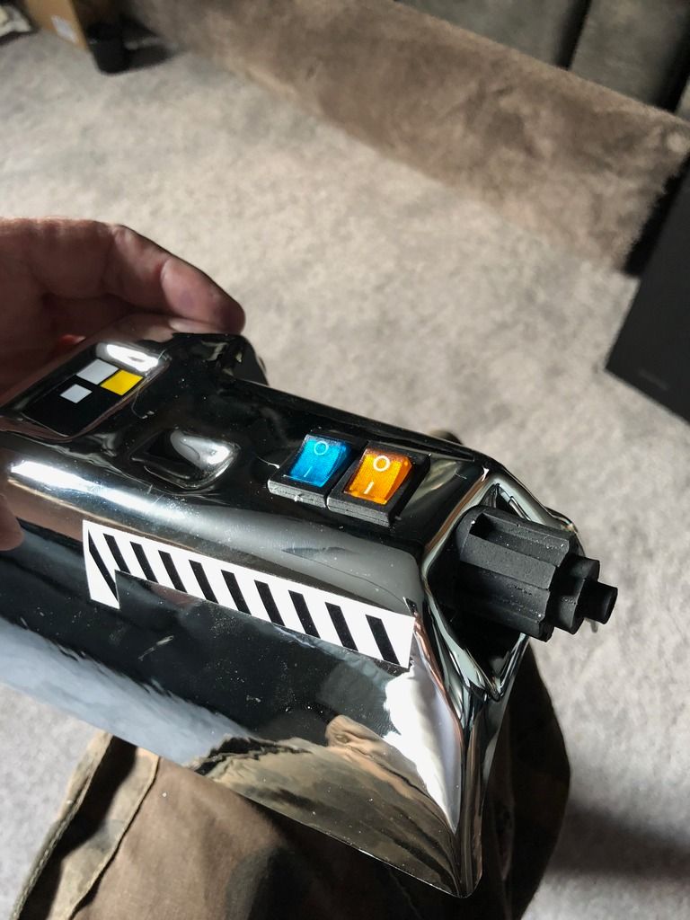
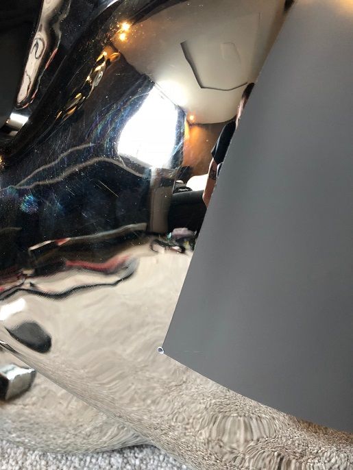
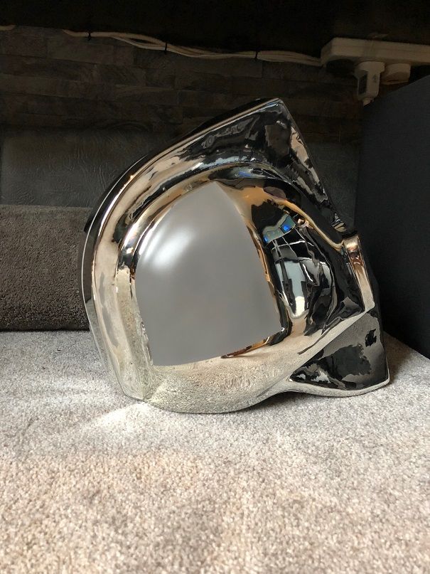
And two on the bulky side of the Gauntlet making sure I could see them through the helmet...

Image


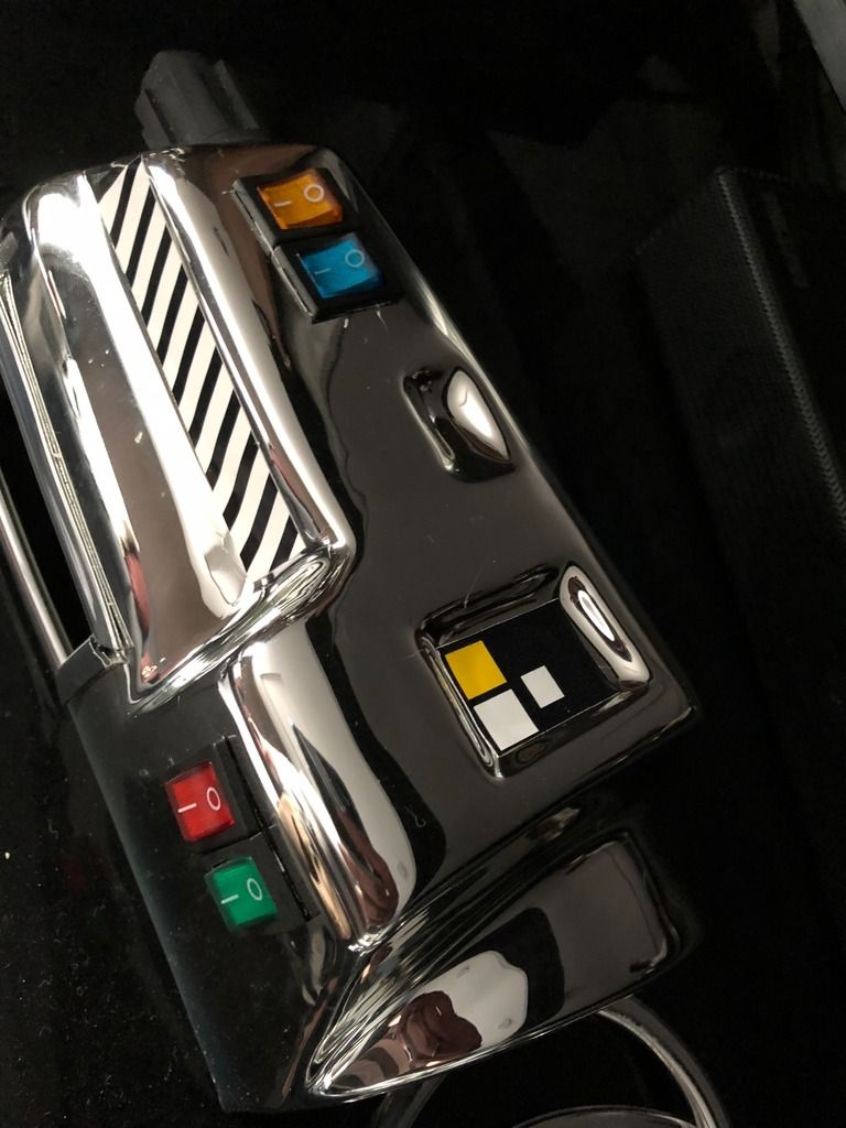
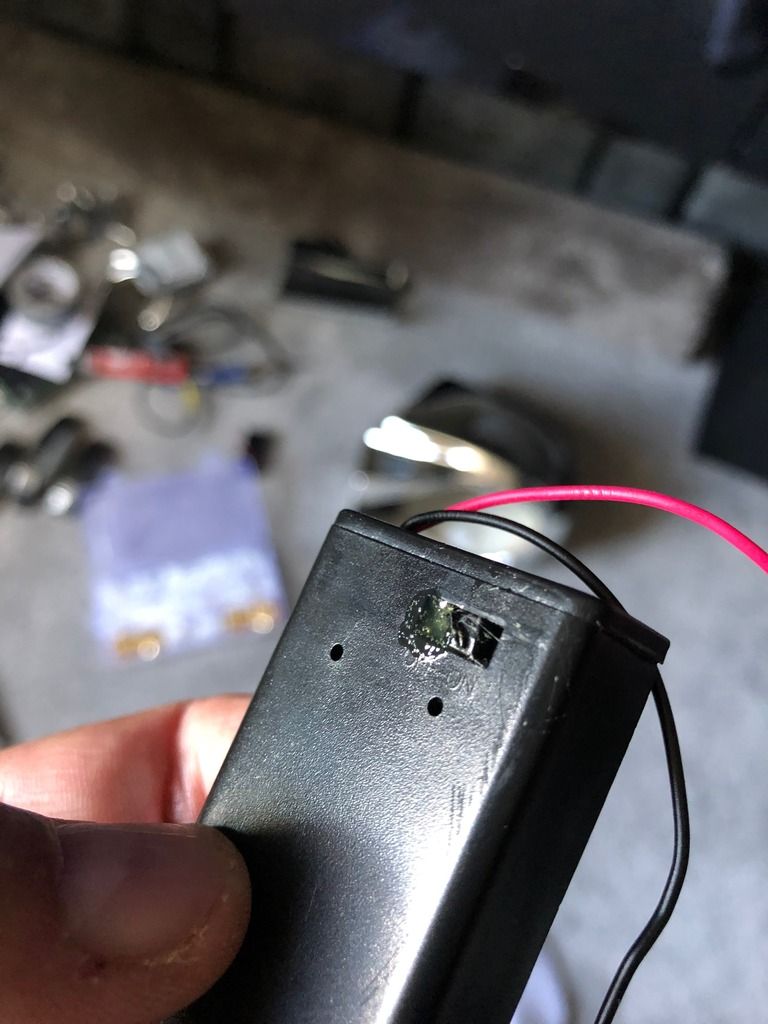
You'll also notice on the latter picture the cut out (which I need to tidy up!) where I'll be placing the MP3 player screen to control the noises and stuff.

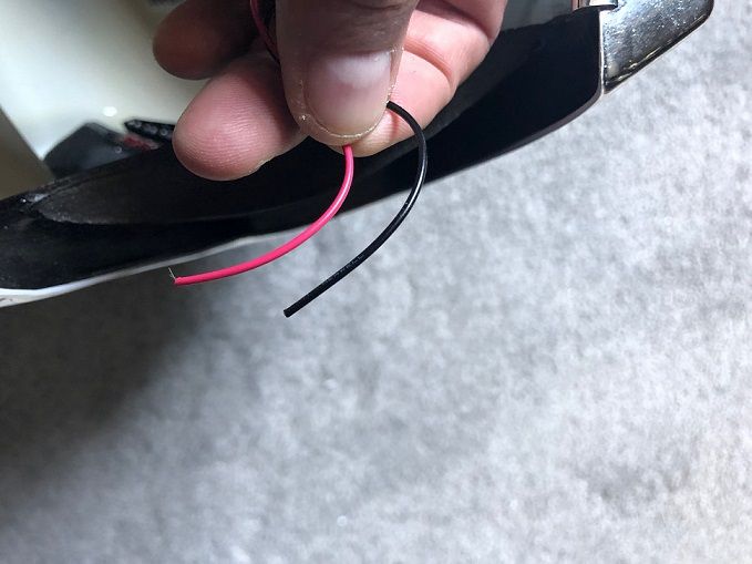
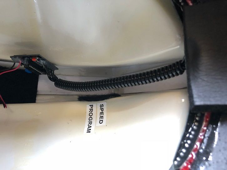
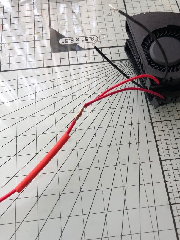
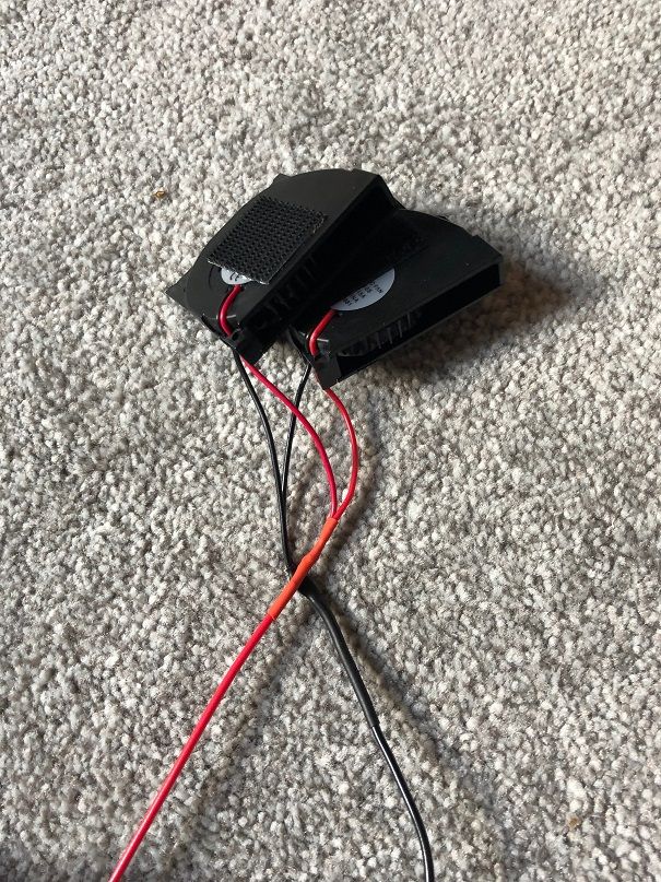
Now these are in place I can start thinking about soldering the wires for positive and negative... and where I'm going to place the 2-3 x PP3 batteries (In Parallel) and how this is going to work based on the wiring diagram above (Inside the gauntlet)


When I've placed all the Gauntlet components, I'll post where I've put them, and how I've wired them up...

Until soon! :cylon:

Mack

Edit.. Although the "styrene" is rather soft, I don't recommend using a crafting knife to cut out the holes for the switches. You'll notice a couple of scratches on the top, where the knife slipped. I've already got the Gauntlet tidied up, and scratches have now gone (It helps working in an auto repair centre as re-chroming is a benefit of the job!) :wink:

User avatar
Cylon-Knight
Site Administrator
Posts: 6419
Joined: Wed Jul 23, 2008 9:32 pm
Location: Kansas City
Contact:

Re: Gutting the inside of a Krop helmet

Post by Cylon-Knight » Sat Sep 01, 2018 1:43 pm

:loveit: :loveit: :loveit:
"All Baseships are now in range to attack the Colonies."
Image

User avatar
MackUK
Phalanx Member
Posts: 86
Joined: Tue Nov 21, 2017 12:43 pm
Location: London, UK

Re: Gutting the inside of a Krop helmet

Post by MackUK » Sun Sep 02, 2018 11:37 am

So now the switches are in place, it's time to work on the helmet itself...

First thing... cut the wires which power the eye

Image


Then thread the wires from the PCB to the eye into 5mm flexi conduit...

Image

Given the PCB has controls which need accessing, I placed the control units facing towards the rear of the helmet... and hot glued the conduit around the side of the eye to keep things tidy... although the board seems exposed, this will be covered to protect the circuits with padding...

Image

When all was done, I'm still able to see through above the of the eye with minimal vision disturbance...

Image


Next on to the fans...

I joined two fans together soldering the pos wires together, and then the neg wires together, (Including the heat shrink to keep things tidy) and included a power cable, which I'll use to connect to a plug in the base of the helmet which in turn will be used to feed the power from the right Gauntlet power supply and switch...

Image

Image

Image

The operating volume of squirrel fans are noisier than those of normal flush fans, so I needed to seal off the mohawk (to enable a steady air-flow from the lower back of the helmet AND use some form of sound deadening... so I used CosPlay foam (double layered) and sealed off the fans except from above the eye (Outlet) and base of the rear of the helmet (Intake). I used this channel to also feed the wires through which will plug into the base of the helmet...

Image

More soon!!!

Mack
:byyourcommand:

User avatar
MackUK
Phalanx Member
Posts: 86
Joined: Tue Nov 21, 2017 12:43 pm
Location: London, UK

Re: Gutting the inside of a Krop helmet

Post by MackUK » Mon Sep 03, 2018 12:57 pm

For the microphones I drilled a 1mm hole either side of the helmet where the grey meets the chrome (the microhone will sit inside the hole). Close up it looks quite discreet, but from a distance you hardly notice them...

Image

&

Image

User avatar
MackUK
Phalanx Member
Posts: 86
Joined: Tue Nov 21, 2017 12:43 pm
Location: London, UK

Re: Gutting the inside of a Krop helmet

Post by MackUK » Tue Sep 11, 2018 12:35 pm

OK, so I continue with the build after a couple of busy days at work...

Deciding that the right gauntlet wasn't big enough to carry two PP3 battery packs I decided that they would fit comfortably inside the helmet on the lower parts either side of the chin...

This meant two things...

1) there would be more wiring involved to control the functions of the eye and the fans...
2) more stuff to cram into the helmet (but it's all good, as I said, there's a ton of space in there)

So.. First thing to do was hack the PP3 Battery packs by slicing off the on/off switch. I wanted these to be permanently on and face down in the helmet, so I could easily slide off the battery cover as and when I needed to change / recharge the batteries themselves..

Image

In order to ensure they remain on , I used glue to stick the switch to the on position... it looks cruse, but they won't be seen anyway

Image

Post Reply

Return to “Centurion Builders' Forum”

Who is online

Users browsing this forum: No registered users and 4 guests